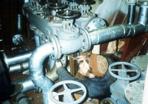
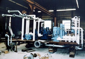
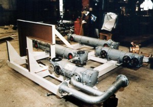
APP01.JPG: In December 1981, George Snaith, the Director of Productivity for the Small Ship Sector, reported favorably on a few National Shipbuilding Research Program (NSRP) publications to the Chairman of British Shipbuilders, the nationalized industry then consisting of 17 shipyards. The publications included “Outfit Planning” – December 1979 (NSRP 0096) and “Product Work Breakdown Structure” – November 1980 (NSRP 0096). George Snaith advised, that his copies result from “…the liaison I have built up with senior officials of the U.S. Maritime Administration…. These reports are quite unique. They represent a corpus of structured know-how describing the best of the state-of-the practiced art of shipbuilding (by IHI) which is without equal. It is quite impossible for me to exaggerate their importance and potential value….” As a consequence, L.D. Chirillo was retained to conduct pertinent lectures for line management in the Small-Ships Sector in May 1982. A remarkable response was managed by the people in the small yard known as Appledore Shipbuilders, on the south shore of the Bristol Channel in Devon. In may 1982, Appledore Shipbuilders was located in a new yard. Prior management had convinced the Government that investment in a new yard, specifically including an enclosed building dock, would cause productivity to increase significantly. The new yard was built near the old one as a turn-key operation. On a given day, the management and work force, as an entity, reported to the new yard. The productivity improvement predicted was not realized because the archaic system-by-system shipbuilding approach remained unchanged. The lectures which included photos of IHI’s integrated hull construction, outfitting and painting, made that clear. The report “Describing Key Changes in Production in the Small Ship Sector,” by George Snaith, updated in March 1983, describes the progress achieved by Appledore Shipbuilders toward zone-orientation in just eight months. This photo and photo APP02 show the traditional piece-by-piece pipe fitting on a machinery-space tank top, which was typical in the new yard in May 1982. The pipe runs are complex, expensive mitered bends are employed, pipe runs do not share common supports, only nominal painting has been performed in process, and there is very poor access for shipbuilding and ship-repair workers.
APP02.JPG: This photo and photo APP01 show the traditional piece-by-piece pipe fitting on a machinery-space tank top, which was typical in the new yard in May 1982. The pipe runs are complex, expensive mitered bends are employed, pipe runs do not share common supports, only nominal painting has been performed in process, and there is very poor access for shipbuilding and ship-repair workers.
APP03.JPG: In May 1982, a single pipe piece with six welded joints excluding the flange welds was common. The cost to fabricate each such pipe piece was extraordinary. The Appledore managers were told, that in IHI, designers have to assign a code to each pipe piece that designates its problem category. Their managers use computer scans to detect expensive-to-make pipe pieces. Afterwards, they take corrective action accordingly.
APP04.JPG: This photo shows a typical unsafe on-board working condition in the new yard in May 1982.
APP05.JPG: This is a general view of the enclosed building dock after the introduction of zone-oriented integrated hull construction, outfitting and painting. A 3,500-ton dredger is shown three and one-half weeks after keel laying. That is a much shorter time for equivalent progress by the former traditional approach. This view does not show the impressive amount of fittings already in place, the ready access to and preparation for completing the machinery space, nor the well-organized construction of the outfitted deckhouse.
APP06.JPG: An orthogonal pipe unit is shown which is one of seven having pipes organized in parallel and sharing common supports, and which is painted except for the finish coat. Even the smallest diameter pipe is included; virtually no pipe is field run, i.e., routed by a pipefitter wherever space is available. Assembly and painting were performed in a shop.
APP07.JPG: This photo shows the outfitting and painting performed on the machinery space overhead, while it is upside down, on an otherwise unused area of the building-dock floor. No scaffolding is needed and all fittings that one worker cannot lift safely, were positioned by a crane. The parallel pipe runs are assembled from seven of the units shown in photo APP06. The large diameter pipes are part of the main-engine exhaust system. Lighting fixtures and the lighting circuits have also been fitted so that following erection of the block, there is no need for temporary lighting systems as had been used in the past.
APP08.JPG: This photo shows an assembled and painted outfit unit. The framework, made from square-steel tubing, is designed to be independent of the hull structure. This simplifies both design and production planning. Pipe bends have been limited to 90- and 45-degrees. Adjustable feet facilitate alignment when the unit is landed on block or on board. Pipe ends have temporary covers to avoid contamination, electric fittings and cables are fitted, and floor-tread plates are in place so that a safe walkway exists immediately upon landing the unit.
APP09.JPG: This photo shows an assembled and painted outfit unit. The framework, made from square-steel tubing, is designed to be independent of the hull structure. This simplifies both design and production planning. Pipe bends have been limited to 90- and 45-degrees. Adjustable feet facilitate alignment when the unit is landed on block or on board. Pipe ends have temporary covers to avoid contamination, electric fittings and cables are fitted, and floor-tread plates are in place so that a safe walkway exists immediately upon landing the unit.
APP10.JPG: This photo shows an assembled and painted outfit unit. The framework, made from square-steel tubing, is designed to be independent of the hull structure. This simplifies both design and production planning. Pipe bends have been limited to 90- and 45-degrees. Adjustable feet facilitate alignment when the unit is landed on block or on board. Pipe ends have temporary covers to avoid contamination, electric fittings and cables are fitted, and floor-tread plates are in place so that a safe walkway exists immediately upon landing the unit.
APP11.JPG: This photo shows an assembled and painted outfit unit. The framework, made from square-steel tubing, is designed to be independent of the hull structure. This simplifies both design and production planning. Pipe bends have been limited to 90- and 45-degrees. Adjustable feet facilitate alignment when the unit is landed on block or on board. Pipe ends have temporary covers to avoid contamination, electric fittings and cables are fitted, and floor-tread plates are in place so that a safe walkway exists immediately upon landing the unit.
APP12.JPG: This photo shows an assembled and painted outfit unit. The framework, made from square-steel tubing, is designed to be independent of the hull structure. This simplifies both design and production planning. Pipe bends have been limited to 90- and 45-degrees. Adjustable feet facilitate alignment when the unit is landed on block or on board. Pipe ends have temporary covers to avoid contamination, electric fittings and cables are fitted, and floor-tread plates are in place so that a safe walkway exists immediately upon landing the unit.
APP13.JPG: This photo shows an assembled and painted outfit unit. The framework, made from square-steel tubing, is designed to be independent of the hull structure. This simplifies both design and production planning. Pipe bends have been limited to 90- and 45-degrees. Adjustable feet facilitate alignment when the unit is landed on block or on board. Pipe ends have temporary covers to avoid contamination, electric fittings and cables are fitted, and floor-tread plates are in place so that a safe walkway exists immediately upon landing the unit.
APP14.JPG: This unit is designed to be mounted on a bulkhead.
APP15.JPG: This photo shows the rather complex dredger machinery space just prior to landing the two main-propulsion engines. Pre-painted pipe units with floor-tread plates in place on them, form an orthogonal arrangement around the main-engine foundations. Other outfit units have already been fitted outboard and forward of them. The structure around the main-engine foundations that will become relatively inaccessible after the engines are landed, is already finish painted. The Snaith report noted, “There are a few features which indicate need for further improvements to ensure more effective, safer work but the achievement so far is a dramatic improvement over previous methods and practice.”
APP16.JPG: When the zone/stage work effort illustrated in photo APP07 was completed, that main-deck block was turned over and during another zone/stage work effort all heavy galley fittings, etc. were welded in place. Then the outfitted deckhouse was landed on that main-deck block in order to create the grand block that is seen here during hull erection. Following erection, the electric cables that had only been fitted inside the deckhouse, had their loose ends uncoiled and pulled into the hull below. The series of photos APP04 through this one, depict an incredibly impressive first-time attempt, by a small shipyard, at zone-oriented integrated hull construction, outfitting and painting. The Snaith report included a section on Further Changes to be Carried Out. Because small-shipyards elsewhere have failed in their attempts to modernize, it is quoted verbatim:
“Although it is self-evident from the captioned photographs that the intrinsic work to fabricate and assemble the outfit of a ship is already lower than that required using traditional methods, nevertheless, there are still greater improvements that can be achieved. This, basically, requires the yard management to lead the pre-production and production teams in extending the good aspects of the experience gained so far and supplementing it with other aspects – as outlined below. Particular attention needs to be paid to the preparation, scheduling and execution of work assignments (packages) to achieve the quantity and quality of output and the co-ordination of work such that waiting time, not intrinsic to the work, is avoided.
“The emphasis of the immediate work on effecting further changes in the methods of organizing and carrying out the work of construction – especially of outfitting – at Appledore Shipbuilders is to emphasize:
• “re-group the design/draughting team to match the major ship zones (engine room, cargo spaces and accommodation) rather than the traditional grouping of steel, outfit, machinery, piping and electrical.
• “ensure earlier identification and ordering of material and equipment to match the zoned construction of steel and outfitting units.
• “improved organization and execution of work involved in the assembly of zoned outfit units and zoned steel units.
• “improved scheduling of work to maintain continuity of work for the groups of workers in the workshops, the building dock and the commissioning quay.
• “introduce line heating methods of complex shape of steel plate accurately, enabling first-time fit up and less correction work.
• “apply accuracy control methods as the way to improve the production processes.
• “establish a new working/operational relationship with the principal subcontractors (heating and ventilation) so that their work schedule matches that required in zone outfitting and the building strategy.
• “improvement in the form and content of the ‘information packages’ (drawings, sorted lists of materials, equipment, fittings, tools, resources)
• ” translate some of the man-time saved in the work of construction into more man-hours effectively used by the pre-production teams to enable further greater savings to be made on the shop floor.
• “promote further the engineering-of-change from within the company by providing the best opportunities (which may involve quality circles) for those able and willing to contribute their knowledge and ideas to achieving further and thereafter continuous improvement in productivity and company performance.
• “design draughting teams to produce composite drawings in full detail. For example, small bore pipework layout shown.
• “rationalization of the number of equipment suppliers and their designs. Development of a vendors standard catalogue and standard specification for use in contract negotiations.
• “devising work packages of manageable size, and establishment of process lanes.
• “further application of Computervision to generate material lists and work instruction drawings.
• “re-organization of management and supervisory structure in line with zone construction and group technology principles.
• “strengthen production engineering effort and the development of standards.
• “further recruitment of planning and shop floor support staff.
• “strengthen feedback from production departments to technical departments.”


