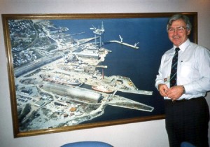
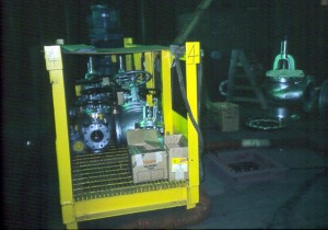
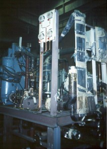
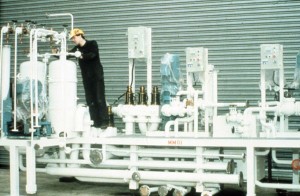
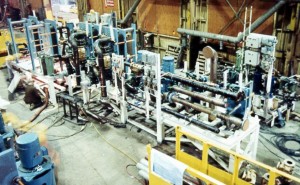
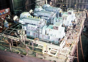
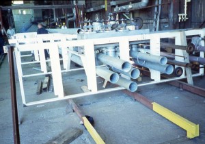
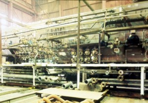
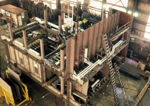
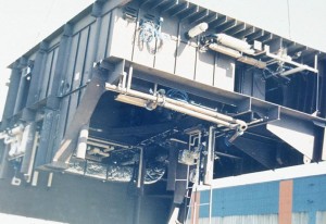
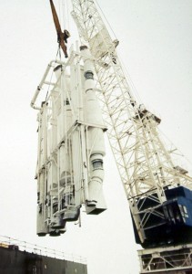
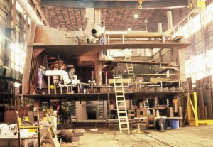
CHA01.JPG: When Donald W. Challinor (1928-1991) became president of Versatile Pacific Corporation’s shipyard division, he was aware of diminishing marketing opportunities with the traditional methods then being employed in both his Vancouver and Victoria shipyards in Canada’s British Columbia. He heard that something different was being done in the United Kingdom so he traveled to the London office of British Shipbuilders to inquire. There he was told, “Yes we are doing something different and the best place for you to see it is in the yard known as Appledore Shipbuilders in Devon.”
Thus, Don Challinor traveled further, four-hours by rail and auto, and walked in on Appledore’s first effort at zone-oriented integrated hull construction, outfitting and painting that is described in photos APP01 through 16. Impressed, he asked, “Who taught you this approach?” An Appledore manager replied, “A fellow who lives near you, Lou Chirillo.” Don Challinor wasted no time. He was determined to apply the manifestly better methods. He retained L.D. Chirillo to perform the same lectures in both his Vancouver and Victoria shipyards, but he also did a few things that were unique. He arranged for the lecture to be given three times in each of his two yards. In both places senior managers were addressed first. Don Challinor sat in the center of the front row both times. Immediately afterwards he privately interviewed each attendee. The following account is typical with Don Challinor starting:
“What did you think of yesterday’s lecture?”
“It was very interesting.”
“I didn’t mean for you to be entertained. Don’t you think we should be adopting that zonal approach for outfitting?”
“We were doing that when I was in Cammel Laird fifteen-years ago.”
“Mr. Chirillo addressed that. He said it was the consequence of planning after system-by-system detail-design drawings were completed. Afterwards, planners, in a time and man-hour consuming process, did the best they could by pulling off bits of information from number of drawings in order to devise a work package for on-unit or on-block outfitting. What he recommended was defining zones and stages, i.e., planning, before detail-design starts. Then designer-produced composites show what is to be outfitted on unit, on block and on board. Isn’t that different from your Cammel Laird experience.”
“Yes.”
“Then shouldn’t we try what he recommended.”
“I suppose we should.”
Don Challinor also attended each of the second round of lectures that were for middle managers and each of the third that were for the lowest-level supervision and union representatives. When asked why he was attending the same lecture repeatedly, he replied, “I want everyone to know how important this is to me!”
Just as he did for his senior managers, after each lecture he separately interviewed the lower-ranking people who were likely to influence their peers. In one of the yards, he fired a shop manager who insisted on using the old approach.
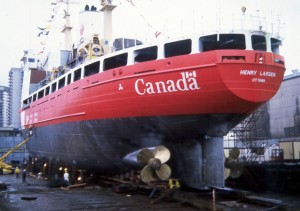
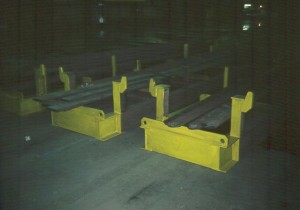
CHA02.JPG: Versatile Pacific’s first application of zone-oriented integrated hull construction, outfitting and painting was for the construction of two difficult-to-build Type 1100 icebreakers, one in each yard. In this photo, note should be made of hull fairness. One senior manager, brought up in the British shipbuilding industry and who was at the outset skeptical of the zonal approach, said at this launching, “I never saw a ship go together as easy as this one did!” Don Challinor freely shared this experience as manifested by the following excerpts from a paper that is rare because it was written by a chief executive:
———–
by D.W. Challinor, Versatile Pacific Shipyards, Inc.
presented to the CSSRA Annual Technical Conference, 10-12 February 1986 in Quebec
INTRODUCTION
In 1982, the foreign ship repair business, which had been the mainstay of our operations, took a severe downturn, so it became increasingly obvious that, as time went by, we would have to make our new shipbuilding division more profitable.
A survey of other efficient shipyards around the world showed we were far behind in many areas.
After having finalized our contract to build two1100 class navaids light icebreakers for the Coast Guard, the decision was made to upgrade our shipbuilding technology as fast as possible. In 1984, we retained Lou Chirillo to lecture to our various levels of management on advanced shipbuilding technology and contracted with IHI to train some of our employees in certain special skills. Also, we sent a number of operations management and supervisory personnel to Japan to see first hand the changes that were required.
Our initial construction schedule was along traditional lines using minimal outfitting, but once having decided to adopt the new zonal outfitting by stage methodology, we had to change the schedule to allow for much more engineering up front before construction could begin.
DESCRIPTION OF THE CCG TYPE 1100 NAVAIDS VESSEL
The type 1100 Navaids vessel has a length overall of 83 metres, a beam of 16.2 metres and a depth of 7.75 metres. The design draft is 6 metres and the displacement at this draft is 4,662 tonnes.
The vessel’s propulsion machinery consists of three…diesel engines each directly coupled to generator.
Propeller speed is controlled by cycloconverters which allows stepless speed variations….
The vessel has accommodation for a crew of 52 and has the latest navigational equipment.
DRAWINGS
The Electrical Drawing Office concentrated on maximizing preoutfit within zones and minimizing cross-overs between zones. In many cases this enabled ships lighting within a zone to be utilized immediately after erection.
Steel drawings were provided for individual units or blocks….
One of the major problems for Drawing Offices generated by the new technology is the need to concentrate extensively in a compressed time frame the production of drawings and requisitioning of materials.
STEEL WORK BREAKDOWN
The ship was broken into 53 steel blocks ranging up to 80 tonnes for a total hull and superstructure net weight of 1,818 tonnes.
The main hull was constructed with 400mm transverse framing utilizing offset bulb plate in the midbody section and EH-36 steel flat-bar framing in the forward and after ends. Shell plating in the forward and after ends and ice belt region consisted of EH-36 steel in thickness up to 41mm, but in general, 31.5mm on the bow and on the stern.
Main hull and superstructure units averaged 50 tonnes…. All units were completely fabricated and surveyed prior to leaving the shop. Erection butts and seams were located where possible for convenient access as well as minimal interference to outfit activities. Fabrication was completed utilizing sub-assemblies up to 20 tonnes which were incorporated into larger block units for preoutfiting prior to erection. In most cases seatings, penetrations and minor steel outfit were added prior to leaving the shop. The fabrication sequence plan endeavoured to take advantage of downhand fitting and welding while maximizing use of automatic and semi-automatic equipment. Where practical, piping and wireways were fitted prior to closing up units.
Erection of outfitted units were scheduled so as to close off weather-susceptible units quickly, protecting Blue Sky outfitted equipment and systems. Unit connections were faired, welded and surveyed in quick succession so as to facilitate the interconnection of outfit systems in a progressive manner. Overall, hull construction was completed on schedule with virtually no rework or unscheduled delays, allowing the final stages of outfitting to continue unencumbered by steelwork activities.
ACCURACY CONTROL
Line heating was used to form certain complex plates and curvature of other formed plates to reduce fitting tolerances so as to eliminate the use of strong backs and welded clips. This improved fitment helped to eliminate locked-in stresses, thus ensuring accuracy and reliability of the subassembly to fit into the unit.
MATERIALS – PLALLETIZATION AND PURCHASING
This aspect of the program was most critical and required radical rethinking of our previous procedures. Bulk ordering and equipment requisitions were about the same, but other materials were ordered earlier because of the increased amount of engineering in various zones. Palletization, which should normally begin in the drawing offices was largely carried out by the production planning group who did an excellent job of bringing all the materials together for the zonal outfitting.
ZONAL OUTFITTING
The advantage to production of outfitting by zones can be felt immediately with the early start of outfitting by a small number of experienced marine tradesmen, with a gradual controlled build up of the labor force, with the peak well below the numbers used in the old traditional methods. This has eliminated the need to bring in a large number of inexperienced low calibre tradesmen which has usually resulted in lower productivity.
Steel subassembly of unit outfit was predetermined as a work package together with man-hours by trade, which was then allocated to the lead trade for execution in accordance with our agreed schedule for starting and completion. The work packages were limited between 200 and 500 man-hours in order to outfit in stages where possible, and to maintain better cost control of the project.
All components to be fitted were supplied to the job site in packages either from stores or trade shops where they had been manufactured. We endeavoured to apply group technology where practical to assemble parts together that would lend themselves to production line manufacturing. This was effective for pipe components, ventilation trunking, wireways, steel doors and shell framing.
When one considers that electrical man-hours on this diesel electric ship are approximately one-third of the hull steel hours, we feel we have made a good start on electrical zonal outfit by achieving approximately 25% of wiring, precut and fitted before erection. The remaining 75% was interzonal cable fitted after erection on the berth.
Most of the accommodation outfit units were 100% complete before erection except for certain wiring, ceilings and bulkheads. Painting was completed in some cases, but in others, where outfit and welding had to take place on the other side, painting was done after erection.
UNION ACCEPTANCE
We have made a great effort with our workforce to obtain a better understanding of the implications of not changing our technology.
Most of the changes have been well received (and indeed we have found great enthusiasm) as pipefitters and electricians are now able to work in the plate shops installing fittings in partly prefabricated units. Two years ago this was forbidden. There is also a tacit acceptance of the need to work together as a team with the hard lines of demarcation beginning to fade and becoming fuzzy around the edges.
TERMINOLOGY
In this paper we have used certain terminology which is different to that developed in Japan and in use in the U.S.A., e.g.:
unit = module
block = subassembly
grand block = unit
There is obvious need for our technical committee to get together and agree on the terminology best suited to our industry. Also, as the new Journal of Ship Production produced by SNAME is now widely circulated in Canada, perhaps we should be guided by them.
CONCLUSION
When we introduced advanced shipbuilding technology into our shipyard, we were told it would take 3 years to reach our present level of achievement. Recognizing we were far behind and not having that much time to spend, we changed the targets. The great enthusiasm and cooperation from all our line management and employees has made this 1100 program very successful, but we all recognize we have a long way to go as there are untold opportunities for improvement ahead. With the Japanese as the world’s leading shipbuilders now planning productivity improvements of 45-50% in the next 5 years, it is no time for any of us to rest on our laurels.
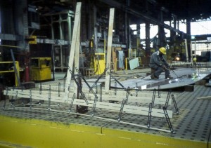
CHA03.JPG: A larger icebreaker, a Type 1200 was also built with modern technology in Versatile Pacific’s Vancouver shipyard. IHI consultants participated in order to further facilitate the transition away from the archaic system-by-system approach.
CHA04.JPG: Line heating to accurately shape curved plates was employed for the first time. The curved hull plates for the Type 1100 were formed with significantly fewer parts-fabrication man-hours than would have been required by the old method of just rolling and/or pressing. Line heating was also used for the type 1200 hull plates, which were fabricated from thicker EH-36 tensile steel. Due to that added thickness more heat input was required and the man-hours comparison showed a tie. However, because of the much greater accuracy achieved by line heating, there were significant man-hour savings in fitting and welding processes during the sub-assembly, block assembly, and hull-erection stages.
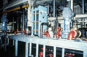
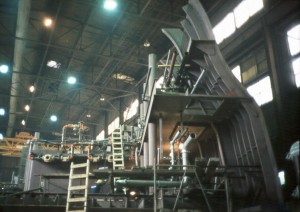
CHA05.JPG: By the mid 1980s both of Versatile Pacific’s yards were producing orthogonal outfit units in a shop. People were working smarter not harder as compared to traditional outfitting on board.
CHA06.JPG: By the mid 1980s both of Versatile Pacific’s yards were producing orthogonal outfit units in a shop. People were working smarter not harder as compared to traditional outfitting on board.
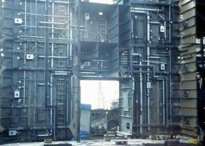
CHA07.JPG: An outfit unit for the uptakes in the Type 1200 icebreaker is shown.
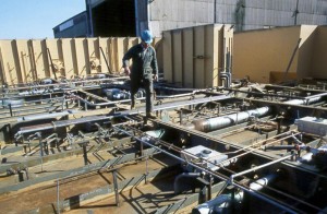
CHA08.JPG: Even the smallest diameter pipe was included in the pallet (work package) for outfitting on block.
CHA09.JPG: An outfitted block is shown during turnover. The objective is to get rid of the debris left behind after “stick” welding many fittings when the block was upside down.
CHA10.JPG: An outfitted block is shown during turnover. The objective is to get rid of the debris left behind after “stick” welding many fittings when the block was upside down.
CHA11.JPG: In 1986 Don Challinor became president and CEO of Versatile Davie in Levis, Quebec and immediately set out to change attitudes and increase productivity as he had in Versatile’s British Columbia shipyards. Not long after his arrival, the yard was acquired by Marine Industries Limited (MIL). The yard became MIL Davie. Don Challinor’s approach was the same as described for photo CHA01, i.e., retaining L.D. Chirillo to explain the logic and principles of IHI’s methods separately to top managers, middle managers, etc. Afterwards, as he did in the west-coast shipyards, he interviewed key attendees one by one. Apparently the engineering manager did not express an intention to cooperate; Don Challinor replaced him.
Also, the labor union and the community had successfully lobbied along with the company for the Canadian Government to award a contract for construction of a second 179m by 25m by 8.4m, 27,230 gross-ton open-sea ferry Joseph and Clara Smallwood. The first ferry had been built with traditional Davie methods and at a loss. Per the book Tall Ships and Tankers, the History of the Davie Shipbuilders by Eileen Reid Marcil, 1997, ISBN 0-7710-5666-4: “Challinor tackled the problem of productivity. This required both the introduction of state-of-the-art technology and a complete change of attitude towards shipbuilding on the part of all employees. Resisting strong pressure from traditionalists who wanted work on the second ferry to start immediately, Challinor convinced the MIL board that improved shipbuilding methods should be introduced first. He looked to Japanese shipyards as the model to emulate. It was their efficient methods he had successfully introduced in the Burrard-Yarrows shipyard (Versatile Pacific’s two yards in British Columbia).
“Six teams made up of management, engineers, production staff, and union representatives each spent ten days studying the advanced techniques of modular construction employed at the Tokyo and Kure shipyards of Ishikawajima-Harima Heavy Industries (IHI), one of Japan’s largest and most modern shipbuilders. They saw for themselves the giant strides that had been made in shipbuilding over the previous twenty years and were quick to realize that the Davie shipyard could, and must, be made far more efficient.
“According to Michael Ayre (a Davie VP), who headed one of the teams, these visits marked the beginning of a new relationship between union and management, based on the realization that the shipyard’s future prosperity was their shared concern and responsibility.”
Don Challinor emphasized production control through control of material and organized work flows. Davie workers, aided by IHI consultants, assimilated the new techniques, such as line heating for accurately shaping curved hull parts, and quickly demonstrated command of the more effective methods. They achieved unprecedented amounts of outfitting and painting work in shops, particularly for work on overheads when they are upside down. Improvements in safety and productivity during construction of SMALLWOOD more than justified the increased investment in planning and design. Since there will never be a return to Davie’s traditional methods, much of the cost for introducing the modern approach, particularly the investment in design as an aspect of planning, qualifies as a capital investment from which all subsequent Davie projects benefit. In other words, Davie invested in an extremely beneficial transformation in its corporate culture from which there will be no return. Davie employees have been worker smarter, not harder, ever since.
In 1989, Don Challinor received the William M. Kennedy Award from The Society of Naval Architects and Marine Engineers “…for outstanding service and contribution in the development of systems and planning as applied to Shipbuilding and Ship Repair.”
CHA12.JPG: As a consequence of producing detail and arrangement drawings for distributive-systems by zone/stage in the same sequence planned for production implementation, locations and diameters of holes for penetrations were available in time to N/C cut them during parts fabrication. Previously, many man-hours were spent on block or on board, sometimes from scaffolding, in laying-out, gas cutting by hand and cleaning-up.
CHA13.JPG: Fabricated hull parts, longitudinals are shown, are palletized, i.e., grouped and delivered to a work site for manufacture of each subassembly.
CHA14.JPG: MIL Davie also adopted the IHI-developed line-heating methods, i.e., systematic heating and cooling, for accurately shaping curved parts. Adjustable sightline templates appear in the foreground.
CH15.JPG: With the assistance of IHI consultants, MIL Davie planners devised block boundaries that facilitated extensive outfitting on block.
CHA16.JPG: With the assistance of IHI consultants, MIL Davie planners devised block boundaries that facilitated extensive outfitting on block.
CHA17.JPG: With the assistance of IHI consultants, MIL Davie planners devised block boundaries that facilitated extensive outfitting on block. A similar block is shown during turnover.
CHA18.JPG: Material control per pipe piece significantly improved pipe-shop productivity and reduced material losses. Each plastic box contains the fitting required for one pipe piece. Each is supplemented by precut pipe lengths in order to fulfill a material list per pipe piece (MLP). Pipe-piece production is being controlled through control of material.
CHA19.JPG: MIL Davie’s pipe shop was rearranged in order to facilitate pipe piece family manufacturing (PPFM) and was equipped with new pipe benders that have the capability to accurately bend pipe pieces after flanges are fitted.
CH20.JPG: Per PPFM (pipe piece family manufacturing), MIL Davie’s pipe shop assumed the responsibility to palletize completed pipe pieces as required to assemble an outfit unit, a block or a zone during a specific stage on board, even for a multiplicity of systems.
CHA21.JPG: Fittings, such as valves, are palletized by warehousemen. Their portion of each pallet is scheduled for delivery to an assembly site at the same time as the pipe-shop’s contribution.
CHA22.JPG: An outfit unit is shown which required coordinated contributions of the pipe pieces by the pipe shop, of other fittings by the warehouse, and of the rectangular tank by a subcontractor or by an in-house job-shop that does not interfere with rationalized hull-construction work flows.
CHA23.JPG: Relatively delicate instruments and associated tubing are fitted in a MIL Davie shop. Such work on board is avoided as much as possible.
CHA24.JPG: An IHI-style orthogonal units is shown in a shop.
CHA25.JPG: A painted outfit unit is shown in a shop.
CHA26.JPG: Outfitting on an upside-down block. MIL Davie people are working the smart way. Before Don Challinor introduced the IHI approach, in the wintertime much of this work was performed in very cold hulls with the fitters working the “Michelangelo” way, i.e., with their arms raised over their heads.
CHA27.JPG: Outfitting on an upside-down block. MIL Davie people are working the smart way. Before Don Challinor introduced the IHI approach, in the wintertime much of this work was performed in very cold hulls with the fitters working the “Michelangelo” way, i.e., with their arms raised over their heads.
CHA28.JPG: Outfitting on an upside-down block. MIL Davie people are working the smart way. Before Don Challinor introduced the IHI approach, in the wintertime much of this work was performed in very cold hulls with the fitters working the “Michelangelo” way, i.e., with their arms raised over their heads.
CHA29.JPG: The insulators were especially pleased with the shift to working down hand on block. Before, in addition to the discomfort of working with arms over their heads, irritating fiberglass particles were constantly raining down on them. Further, they no longer have to carry all of their bulky material on board.
CHA30.JPG: A transporter is shown removing an outfitted and painted block from a shop.
CHA31.JPG: Some tank-top blocks were joined in a shop to create grand blocks upon which a great amount of fitting work was accomplished.
CHA32.JPG: Some tank-top blocks were joined in a shop to create grand blocks upon which a great amount of fitting work was accomplished.
CHA33.JPG: Some tank-top blocks were joined in a shop to create grand blocks upon which a great amount of fitting work was accomplished.
CHA34.JPG: The ferry design featured a relatively long parallel-pipe arrangement that required a number of pipe units, one of which is shown during its assembly.
CHA35.JPG: The units were joined together in a shop and attached to blocks that consisted of portions of transverse bulkheads which contained all of the penetration fittings.
CHA36.JPG: The parallel-pipe arrangement led to bulkhead No. 11, which featured many fittings and many penetrations. All of the penetrations were N/C cut during parts fabrication. Bulkhead assembly and all fitting work on it was accomplished in a shop with enormous savings as compared to the traditional practice where virtually all of that work would have been performed on a building berth, sometimes during inclement weather.
CHA37.JPG: The outfitted and painted bulkhead No. 11 is shown after being erected. Also, the painted parallel-pipe arrangement is shown after being blue-sky landed.
CHA38.JPG: The orthogonal outfit unit shown, has just been blue-sky landed.
CHA39.JPG: Ideal integrated hull construction, outfitting and painting is manifested during erection of the ferry.
CHA40.JPG: Ideal integrated hull construction, outfitting and painting is manifested during erection of the ferry.
CHA41.JPG: A machinery-space overhead is shown being landed during hull erection. Much outfitting, including some electric cable pulled into position when the block was upside down, and painting took place in a shop. This photo demonstrates that MIL Davie had achieved unprecedented levels of safety, quality, and productivity because of the rather sudden input of modern shipbuilding technology.
CHA42.JPG: Outfitting of a typical upper-deck block is shown.
CHA43.JPG: Outfitting of a typical upper-deck block is shown.
CHA44.JPG: Erection of an outfitted upper-deck block is shown.
CHA45.JPG: Hoisting an already painted outfit unit for Smallwood’s uptakes, is shown.


